
Hi
My name is Joel, and I’m currently a 3rd-year robotics engineering student in India, in the semester we had to do a mini-project, and we decided on creating an All-terrain Rover so while doing some research we came across your product and we like your design choice. If possible, can you guide us on designing a rocker-bogie mechanism similar to that used in the LeoRover? Specifically, I am interested in understanding the fundamental design principles, materials, and components needed, and any potential challenges to consider when building such a mechanism.
1 Like
Hi, sorry I haven’t replied to your email yet. Let’s continue the conversation here and it’s actually a topic potentially interesting to everyone.
I’ll just start quickly here and after I find more time I’ll hopefully extend.
Rocker-bogie - the design we use is a modified 4-wheel version of the JPL’s one used in the rovers, meaning there’s no passive bogie in the system, only the rocker mechanism.
You’re hanging the whole body of the rover on one axis and then support it with second point not to let it flip.
In Leo Rover there’s a differential bar and two pushrods (one per each side) to support the body. Hope you’ll find more diagrams etc in the internet.
Mechanically this design means there are only 3 points where the body of the rover are hinged - the main axis and the differential bar axis. Even in this small scale rover the main axis covers quite high forces and momentum - imagine the situation when you for ex try to push one wheel (axially) with your hands - you’re producing a momentum equal to the force x 1/2 distance between the wheels. These can go to 10-20Nm trying to bend the axis.
As for the differential bar, the boundary situation is when you put all the payload on the far side of the rover resulting in a momentum needed to be balanced by both the bar and the differential axis itself - for ex. putting 5kg moved far to the rear results in 250N in the system.
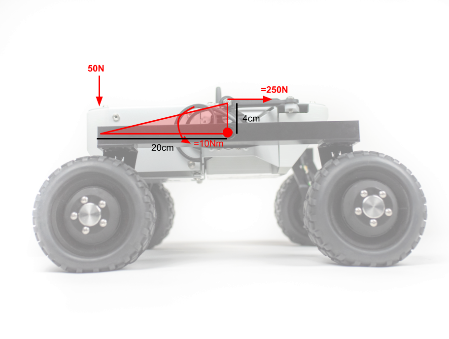
In this scale, go with 3-4mm steel anywhere you think it needs to be reinforced. It’s actually more about the suspension lateral stiffness than strength, so use as stiff materials as can be.
If you have any questions, feel free.
1 Like
Hi, we would like to express our sincere gratitude for your prompt response and the invaluable resources you provided. Thanks to your assistance, our mini-project development was a success, and we are excited to continue working on it as our final-year engineering project.
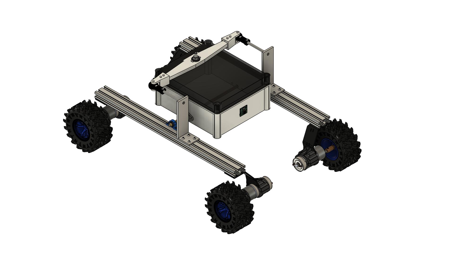
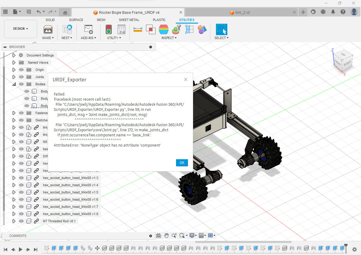
As we move forward, we are now focusing on 3D Mapping and autonomous navigation using ROS Stack, specifically ROS Noetic. We have successfully created a CAD model of our rover using Fusion 360 but are encountering challenges in converting it into a URDF file format for simulation purposes. This is the error we came across. We kindly request your guidance in creating a proper URDF file and SDF file for our rover.
Additionally, we would greatly appreciate any insights or recommendations on optimizing the computation workload during the mapping process. Currently, we are utilizing a Raspberry Pi 4 (8GB), Kinect Sensor V1, and RTAB-Map for 3D mapping. However, we have observed subpar performance and believe there is room for improvement.
1 Like